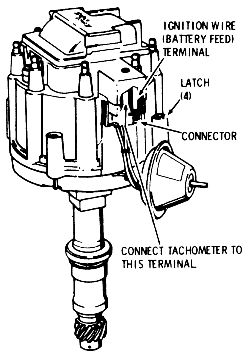
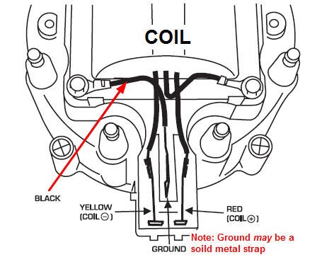
Chevy hei ignition wiring diagram is one of the pictures we located online from reliable sources. Unplug the primary wire plug from the hei distributor.
Make up a 12 gauge wire with an in line 20 amp fuse.

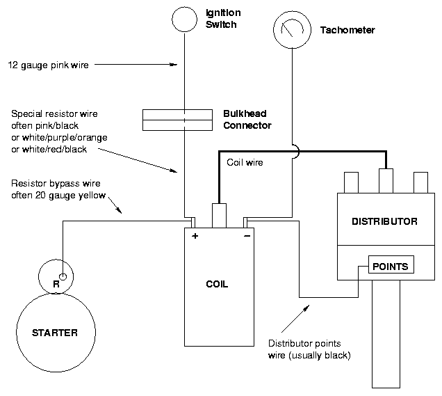
Hei ignition wiring diagram. The first diagram shows a typical stock points system. Wiring for typical points ignition system. Use a flat blade screwdriver to turn the two distributor hold down screws 180 degrees and pull the distributor cap away from the distributor.
All my videos are in 1080p so check that out just an idea on how the gm hei electronic distributor is wired up thanks for watching and please subscribe. It reveals the elements of the circuit as streamlined forms and the power and signal links in between the devices. Variety of gm hei distributor wiring schematic.
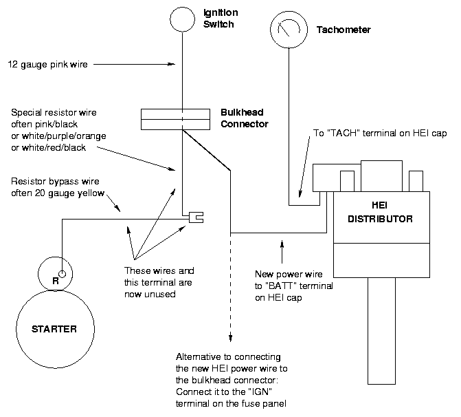
Chevy hei ignition wiring diagram the very first diagram shows a common stock points system. Chevy hei distributor tach wiring welcome to our site this is images about chevy hei distributor tach wiring posted by ella brouillard in chevy category on aug 10 2019. Note that the new hei power wire can be connected to the bulkhead connector as described in the above paragraph or it can be routed to the ign terminal found on most fuse panels.
Connect that wire from the ignition switch directly to the bat position on the hei. You can also find other images like chevy wiring diagram chevy parts diagram chevy replacement parts chevy electrical diagram chevy repair manuals chevy engine diagram chevy engine scheme diagram chevy wiring harness. The second diagram shows where the wires go when converting to hei.
Assortment of chevy hei distributor wiring diagram. Locate the distributors rotor button under the cap and determine its direction. Each diagram thats requested must be hand selected and sent.
A wiring diagram is a streamlined conventional pictorial depiction of an electrical circuit. A wiring diagram is a streamlined traditional photographic depiction of an electrical circuit. How to wire gm hei distributor to msd.
The easiest way to do it and the way i did mine is to find a connection on the back side of the ignition switch that has 12v when the key is in the start and in the run position. It reveals the elements of the circuit as simplified shapes and the power as well as signal links between the tools.
 Chevy 350 Hei Ignition Wiring Wiring Diagram Section
  Chevy Hei Ignition Wiring Repair Manual
  Hei Conversion
  Hei Conversion
  Chevy Hei Distributor Wiring Diagram Awesome Hei Ignition Wiring
  Chevy Ignition Fuse Diagram System Wiring Diagram
  Chevy Ignition Wiring Schema Wiring Diagram
  Gm 5 Pin Hei Module Wiring Wiring Diagram